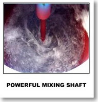
 AGITATOR AGITATOR
The
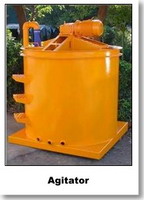
function of the Agitator is to prevent the slurry mixture from setting
while in storage. This is achieved by a rotating mechanism - consisted
of an electric motor with reduction gear rotating a shaft fitted with
three blades at the base of the Agitator tank. The rotating blades keep
the slurry “agitated”.
In an automatic cycle mode, the level of slurry in the Agitator tank is
controlled by a level sensor installed near to the top of the tank.
This prevent overflowing and also the keep the tank full at all time
throughout the cycle.
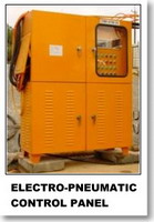
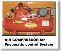
PNEUMATIC SYSTEM
This consists of a air compressor and an electro-pneumatic control
system that controls and operates the pneumatic valves for the water,
cement feeding and the mixing process.
ELECTRICAL POWER SUPPLY AND CONTROL BOARD
The board contains all the electrical equipment needed to power
the various motors as well as the auxiliary equipment, including the
load cell measurement box, and the programmable controller that handles
operation of the automatic cycle.
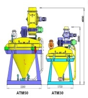
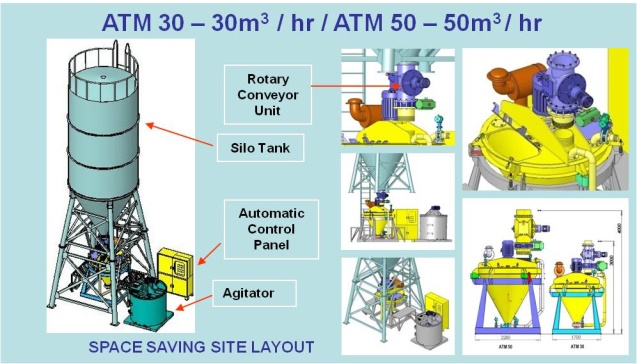
AUTOMATIC TURBO MIXER - ATM 30
|
| SPECIFICATION |
UNITS
|
|
| MODEL |
|
ATM
30
|
|
TURBO MIXER
|
|
|
|
OUTER DIAMETER
|
mm
|
1500
|
|
HEIGHT
|
mm
|
1250
|
|
VOLUME
|
Liter
|
700
|
|
BATCH CAPACITY
|
Liter
|
500
|
|
ELECTRIC MOTOR
|
HP
|
20hp /
4P/1460/1760rpm
|
| AUTOMATIC
PNEUMATIC CONTROL VALVES |
sets |
1 |
|
ROTARY CONVEYOR
|
no.
|
1
|
|
ELECTRONIC LOAD CELLS
|
no.
|
3
|
|
BREAHTER FILTER 6"
|
no.
|
1
|
|
GROSS WEIGHT
|
kg
|
1500
|
|
ELECTRICAL SOURCE
|
|
220V~440V /
50 / 60Hz
|
|
PATENT NO. 064011
|
|
|
|
AUTOMATIC TURBO
MIXER - ATM 50
|
|
SPECIFICATION
|
UNITS
|
|
|
MODEL
|
|
ATM
50
|
|
TURBO
MIXER
|
|
|
|
TANK
VOLUME
|
Liter
|
2600
|
|
BATCH
CAPACITY
|
Liter
|
1500
|
|
ELECTRIC
MOTOR
|
HP
|
40hp /
4P/1460/1760rpm
|
ELECTRO
- PNEUMATIC CONTROL WITH PLC SYSTEM
|
sets |
1 |
|
ROTARY
CONVEYOR
|
no.
|
1
|
|
LOAD
CELLS
|
no.
|
3
|
|
BREAHTER
FILTER 6"
|
no.
|
1
|
|
GROSS
WEIGHT
|
kg
|
2600
|
|
ELECTRICAL
SOURCE
|
|
220V~440V /
50 / 60Hz
|
|
PATENT
NO. 064011
|
|
|
|
 |
|
 HIGHLY PRODUCTIVE MIXING CYCLE TIME
 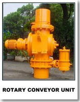 TURBO MIXER
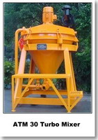 ump which draws water from water tank or
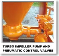 supply line. Once the preset weight is reached, electrical signal from
the load cell on the mixer is sent to close the butterfly valve, thus
stopping the water supply.
supply line. Once the preset weight is reached, electrical signal from
the load cell on the mixer is sent to close the butterfly valve, thus
stopping the water supply.